A focused tolerance strategy helps engineering teams protect function while avoiding unnecessary manufacturing cost and inspection effort.
Key takeaways
Use tolerances to protect function, assembly and inspection—not every nominal dimension.
Define a logical datum structure before adding geometric controls.
Discuss difficult features early when tolerance, access and rigidity interact.
01
General tolerances and critical tolerances serve different jobs
A drawing may use a title-block tolerance for non-critical dimensions while applying specific controls to functional features. This keeps the drawing readable and directs manufacturing attention to the right areas.
02
Build a functional datum structure
Datums should reflect how the component locates in the assembly and how important features relate to one another. An unclear datum scheme can make both machining and inspection unnecessarily difficult.
03
Identify the features that drive performance
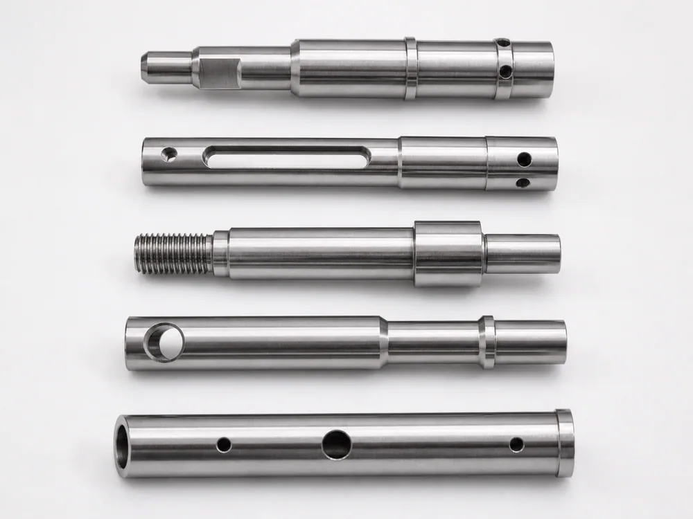
Typical critical features include bearing bores, sealing faces, alignment holes, mating interfaces and locations that control assembly position.
- Size and form of precision bores
- Position between related holes
- Flatness of mounting faces
- Runout of rotating features
- Profile of complex surfaces
04
Consider material, geometry and setup
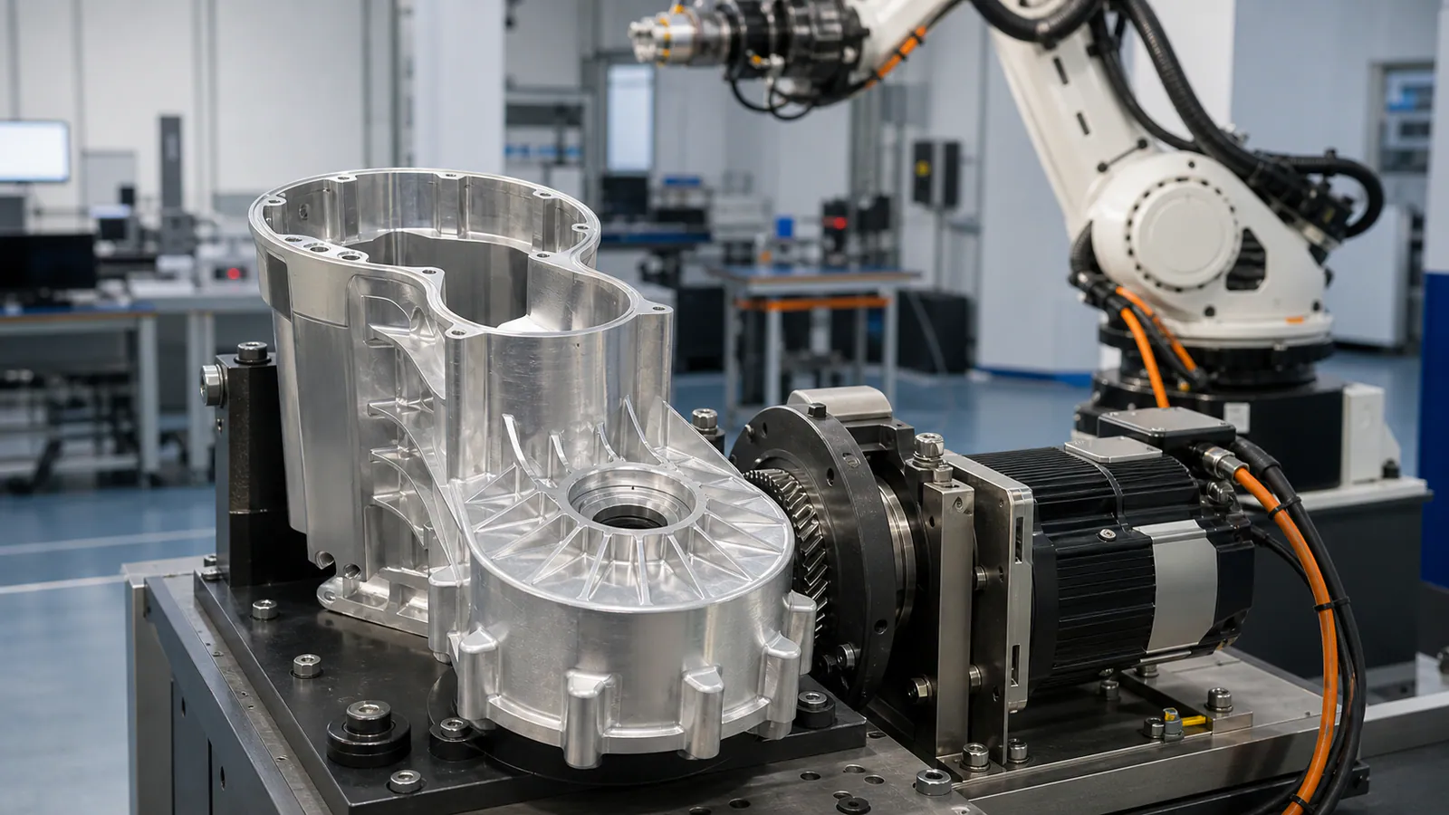
Thin walls, deep pockets, long slender sections and interrupted features respond differently during machining. A tolerance that is routine on a rigid feature may be difficult on a flexible one.
Discuss tolerance expectations together with surface finish, heat treatment and coating because downstream processes can affect final dimensions.
05
Make inspection intent visible
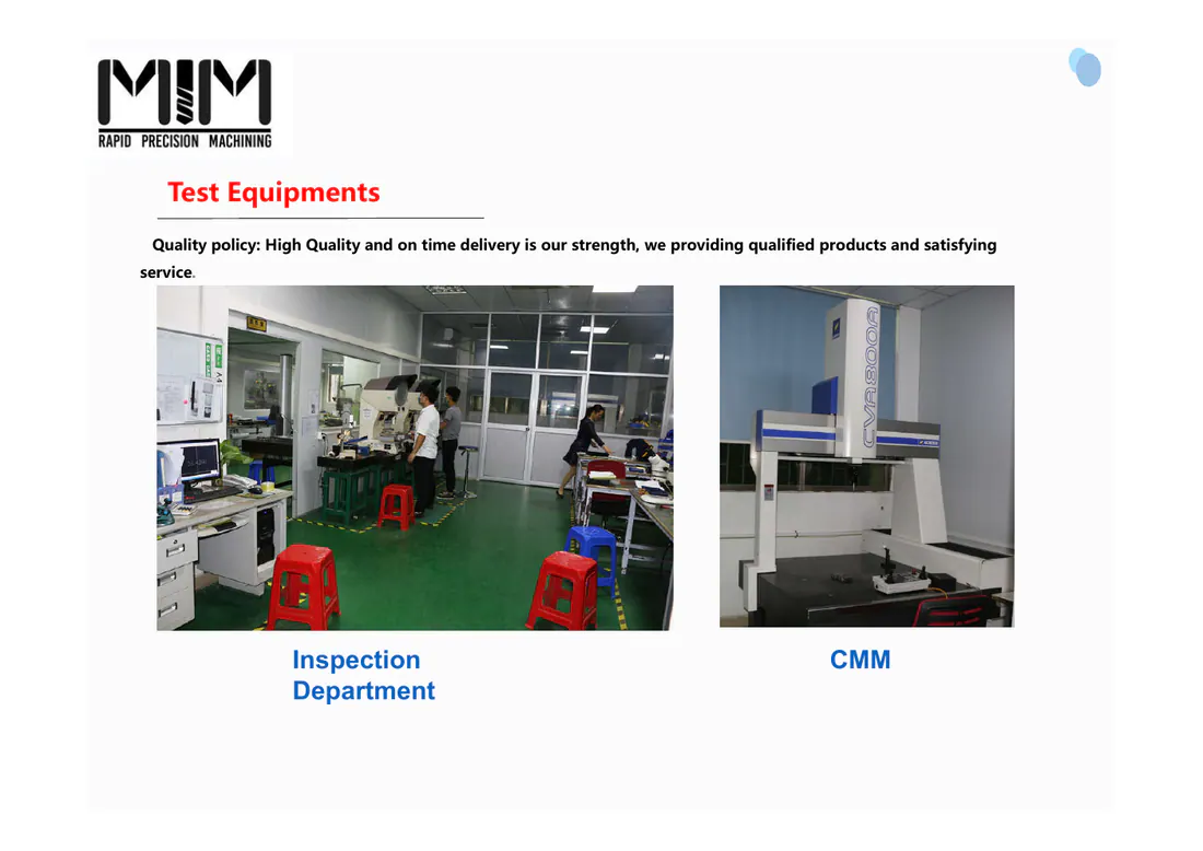
If a dimension requires a particular inspection method or report, state that requirement in the RFQ. The manufacturing and quality plan should be designed together rather than treated as separate steps.

Julie Cai
Project contact connecting international customers with MIM Precision's manufacturing and engineering review team.
Contact Julie